The following will prevent problems with loose crankpins.
Countersink the rear of the crankpin screw holes using a 3mm drill and half screw the 12BA screws home. Using 24 hour epoxy smear the remaining thread and screw the 12BA screws home. Smear a little epoxy over the head for additional security but there should not be a big blob that will catch on wheel rotation. Leave in a warm place for 24 hours to set.
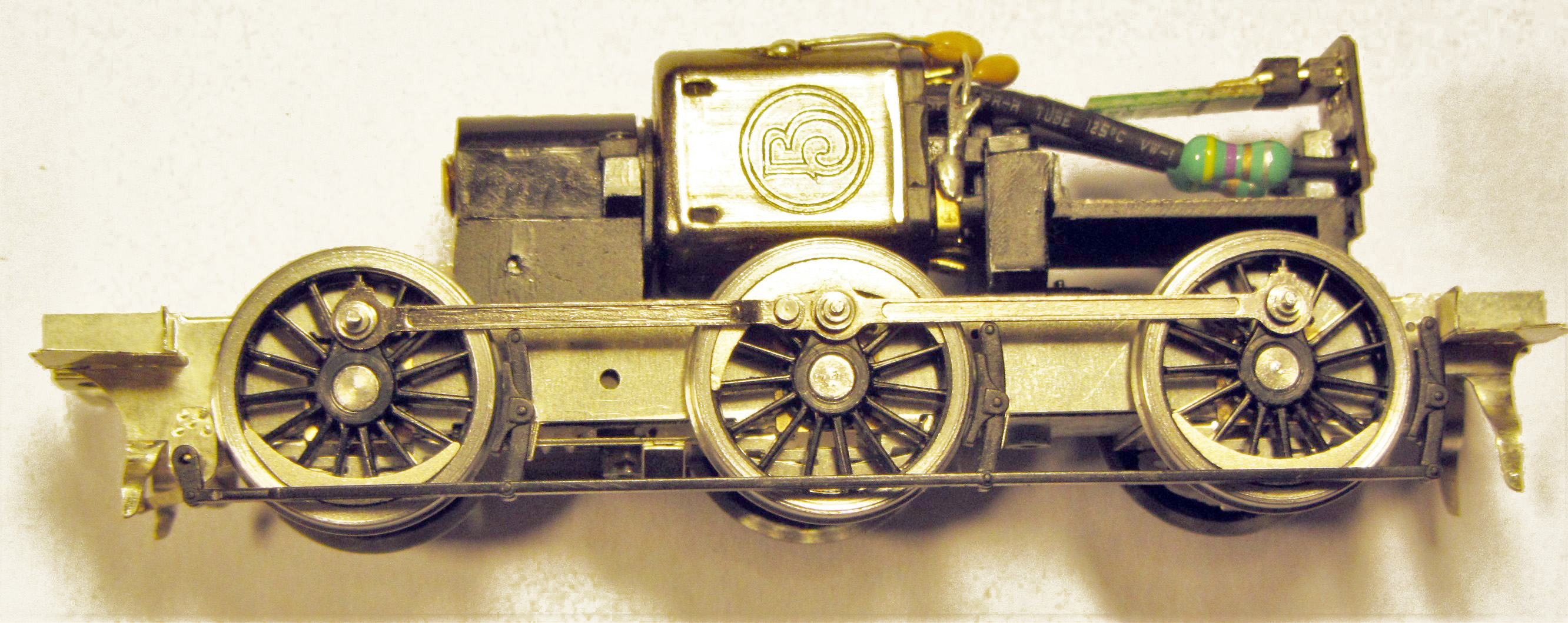
This will retain the screws and stop them from rotating. See photo (before the epoxy was applied) of a larger diameter but similar wheel.

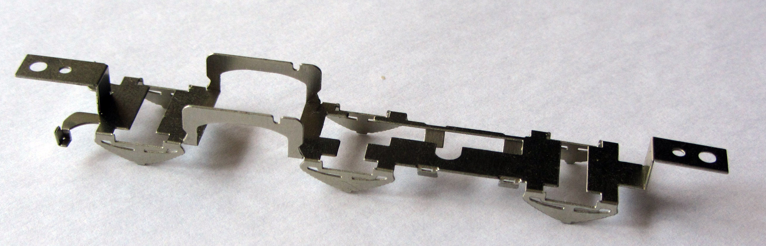
Identify all the items within the main frame [L1], remove them and store them safely.
Remove the loco mainframes [L1] and clean up the residual tabs with a small file.
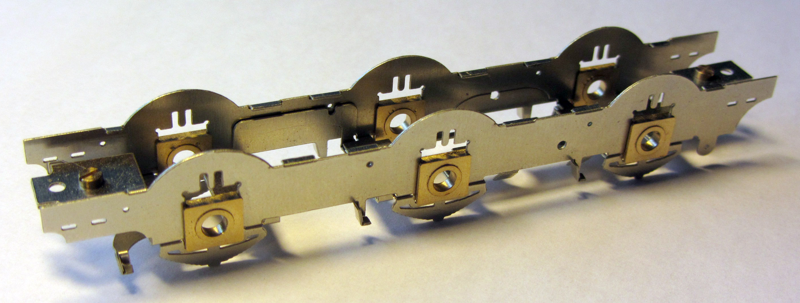
Place the frames flat on the bench and with a thin metal rule fold to produce a ‘U’ section. Either again using a ruler or using a strong pair of pliers, fold up the small sections along the edge of the main frames at 90 degrees.
File off the ‘cusp’ at the end of these top fold sections. Then fold up both end sections making sure that the bends are at right angles. See Photo

Ensure the mainframes fit over the original Bachmann chassis. The frames should sit parallel to the Bachmann frames and not be ‘splayed’ out at the top. If necessary, file the top strips back to ensure this. See Photo.
Remove the mainframes.
Check the fit of the brass bearings into the slots in the mainframes. If tight, using a smooth sharp file lightly file away the cusp equally on both of the edges of the slots until the bearing slides up and down with no binding. It is very important that too much metal is not removed resulting in a sloppy fit – no side play whatsoever is the aim, just a smooth sliding fit.
Fold up the front mounting bracket [L2] and the rear mounting bracket [L3]. Check that they fit in the recess at each end of the Bachmann chassis and that the bottom edges will fit flush with the bottom of the chassis block.

Identify all the items within and attached to the outside of the keep plate [L4], remove them and store them safely. Remove the keep plate [L4]. Fold down the three dummy springs along each side of the keep plate and then fold up the two sections between the leading and middle axles. Finally, fold the four ashpan tabs down until they are at 45 degrees to the keep plate.
Test fit the keeper plate and the frames to the Bachmann chassis, and then put the two mounting brackets in place and ensure that the holes line up with those in the frames and keeper plate. Put a 10 BA screw through the holes nearest to the chassis in the front and back brackets and fit a nut from the bottom. Now fit the assembly to the Bachmann body and make sure that the holes in the assembly match up with the holes in the body. Any misalignment can be corrected with slight adjustment to the bends in the brackets, frames and keep plate. The original Bachmann screws are used to mount the body on the frames.
Unless you are using the replacement etched brake gear, fold up the ‘cups’ on the frame sides and keep plate front that will hold the Bachmann plastic brake hangers so that they form a flat bottom gentle ‘L’ shape with a slight sloping upright.
Again fit the mainframes and brackets to the Bachmann chassis, place the bearings in the slots and check for easy movement. See Photo above.
Temporarily fit the keep plate, using the 10BA screws and nuts. Ensure the bearings slide to the bottom of each slot in the keep plate.
It is now time to fit the front and rear brackets to the chassis.
Firstly, attach the 10BA nuts over the tops of the holes holding them in place using the 10BA screws (if soldering, put oil on the threads to prevent the screws being soldered as well). Apply a smear of epoxy or cyocryanolate to the mating face on the bracket and place in position so that the bottom of the bracket is flush with the bottom on the chassis (remember, any more than a smear will displace the bracket holes for lining up with the frames and keep plate). (We actually did this with the frames mounted on the chassis to hold the brackets in the correct position)
The front 10BA screw will foul the screw on the Bachmann body. Either shorten the front screw level with the top of the nut or remove the Bachmann screw (there are four others holding the body to the footplate.
If the axles catch the side of the chassis block, file away the offending part of the block.
If you are using Alan Gibson wheels you may find the axles are slightly over length for P4. They need to be approximately 22.1 mm long. You will also need to re-use the Bachmann axle gear wheel.
Fit the worm wheel onto the new axle by gentle pushing the gearwheel onto the axle, ensuring that the gear wheel is offset on the axle preferably with the larger shoulder towards the centreline of the chassis. It is essential that the same amount of axle should be protruding each side of the chassis when it is fitted because clearances behind the splashers are small. See photo.
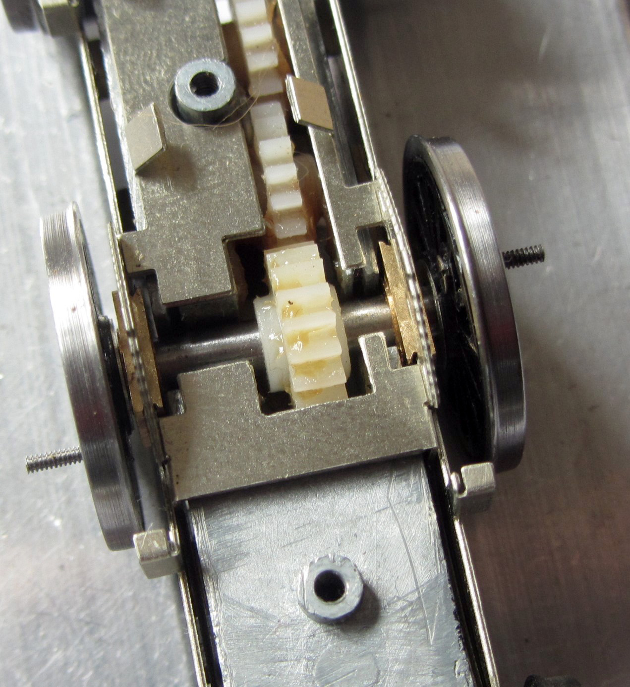

Take the axles and file the sharp edges off the end to a rounded profile. Use a drill bit of around 5mm diameter to chamfer the rear of each wheel axle hole.
These two actions help the axle to ‘centre’ in the wheel when they are pressed on. Mount the bearings on all axles the correct way round, adding any spacing washers required (there will be about 1.2mm lateral movement on an axle with no washers in 18.83 gauge – so not many washers are required). For both EM and P4 we suggest one full washer on each side of the leading and trailing wheels.
Finally, press the wheels on the axles.
Press the wheels home with a back-to-back gauge between the wheels. This gauge should be an interference fit between the wheel backs with no ‘slop’. Ensure this is so by turning each wheel through 90 degrees to check for wobble, and, if present, twist the wheel. The Gibson axles are a little shorter than the distance between wheel bosses (about 0.25mm each side) so do not press them fully home. Quarter the wheels with the right hand wheel leading the left hand wheel by 90 degrees. We do this by setting the driven axle first so a wheel spoke is horizontal on one side and vertical at the other, then each other wheelset fitted is lined up with the horizontal spoke, the chassis turned over very carefully, and the spoke on the other side lined up by eye against those on the driven axle.
Place the bearing springs over the tongues on the frames (a small dab of grease on the spring will keep it in place).
Fit the wheelsets into the main frames and attach the keep plate. See Photo.
Check that the motor turns the middle wheelset with no sign of any binding by applying power to the motor.
Check the wheels spring freely with no binding and test fit to the plastic body.
Remove the springs and put them safe while working on the rods and checking for free running.
Glue or solder the two brake shaft brackets [L5] to the outside of the frame using a piece of 0.6mm wire to ensure alignment.
Push through the four rivets in each guard iron [L6] and [L7] for the front, [L8] and [L9] for the rear and form to a slight ‘S’ shape. Glue or solder the front ones inside the frames at the front (there is a mark on the frames) with the curved face towards the rear, and the rear ones at the back (again there is a mark on the frames) with the curved face towards the front.


Using about a 3mm diameter rod (or an axle or even the shank of a jeweller’s screwdriver) as a former, curve up the half-etched sides of the ash pan [L10] and [L11] with the half-etch to the inside.
If you are going to fit the fully etched version of the brake blocks and hangers it is easiest to do this now - see finishing touches.

Fit the Bachmann coupling rods with the six bushes provided. This will require each hole to be opened up to with a rat-tail round file to accept the bushes, if you are careful, these can be an interference fit. If not, the bushes have to be soldered or glued with epoxy centrally in place and if needed reamed out to take the Gibson crankpin bushes (see photo).
A finer scale solution is to solder up a new set of coupling rods, but this of course takes longer (see finishing touches).

Fit the rods and temporarily secure with a piece of electrical wire sleeve (this does not come unscrewed unlike a proper 14BA nut! We couldn’t find any for the photo so it had to be the 14BA nuts) The rod with the joint (as Photo) is the trailing rod on both sides.
Check that all the wheels now turn without binding when power is applied to the motor and are quartered correctly.
Fit the six springs above the axleboxes to achieve a fully sprung chassis.
Even though theoretically impossible, the front springs can disappear from a completed loco. A drop of 5 minute epoxy at their extreme top where they bear onto the chassis will secure them – trust us on this one!

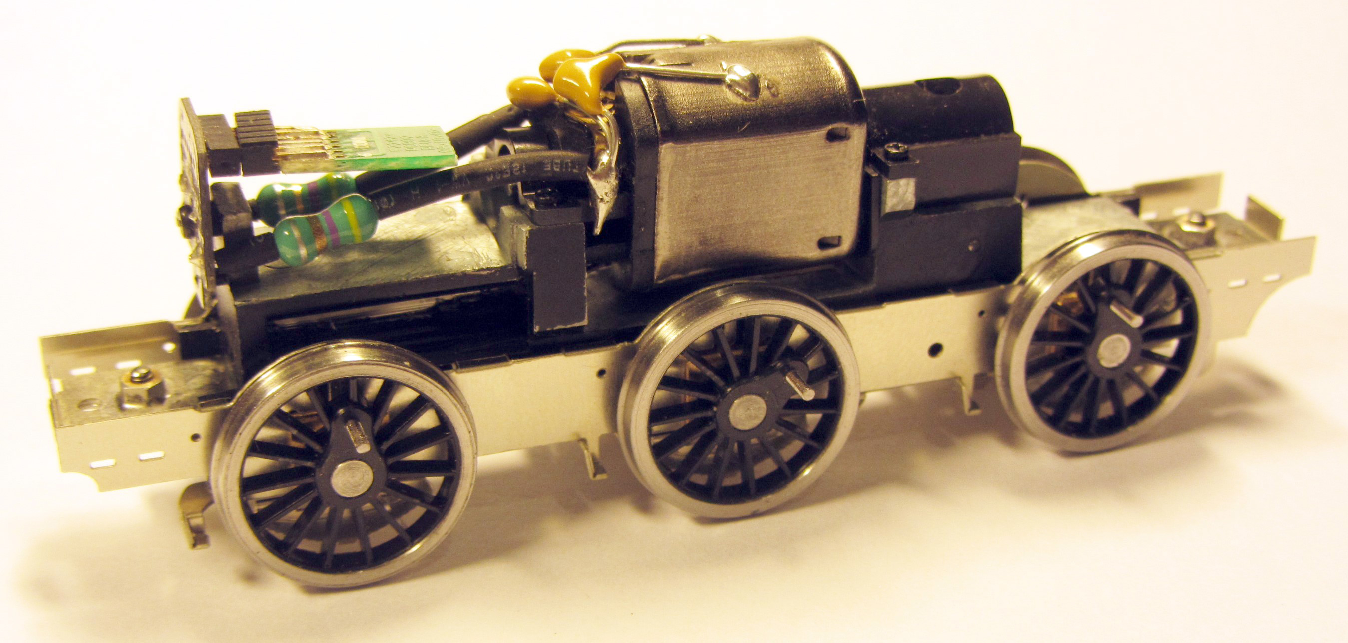
It is not possible to re-use the Bachmann pick-ups so you will need to fabricate your own. Many modellers have their own ideas on pick-ups; this is how we do it. Using a copperclad sleeper (cut to fit between the keeper plate springs) and 33 swg phosphor bronze wire (not supplied but available from Eileen’s Emporium), wind a ‘spring’ shape with extended end. We clamp a fine screwdriver in the vice and, holding the wire one end in the fingers and the other in a pair of round nose pliers, form the spring round the screw driver shaft. Note one pickup is wound clockwise, one anti-clockwise. Solder to the copperclad (gapping it after soldering) as per the photo.

Glue the pick-ups to the chassis keeper plate in the position shown in the photo so they gently press onto the wheel flanges.
Test the polarity and direction of travel with another loco and connect together with brass wire and to the motor with wire.
Test run with and without the body fitted.
When happy, remove the temporary crank pins, shorten the bushes and fit the crankpin bushes (note, if you are going to fit new coupling rods do NOT shorten the bushes). Note: the photo is of a similar arrangement on a different loco.
Re-fit the loco body.

There are several options for the brakes.
The simplest is to re-use the plastic brake blocks, brake pull rods and the brake shaft.
The next is to use the plastic brake blocks with the etched pull rods and brake shaft components, or finally the replacement etched brake gear.
For the second or third options please see finishing touches. The simplest method is shown below.
Carefully cut the brake blocks and brake shaft, complete with pull rods, off the Bachmann keeper plate by sawing next to the main part of the centre solid section. See photo.

Clean up the cut line on the plastic brake hangers to ensure there are no raised edges and if necessary shorten the plastic hanger back ‘studs’ (that fit in the ‘cups’) so they line up with the wheel treads. Remember the chassis is sprung and the wheels will move upwards under the loco weight. Drill a 0.6mm hole in the centre of the brake shaft part way through from the cut edge.
The brake shaft can be assembled as detailed in finishing touches or simply a piece of 0.6mm wire threaded through the holes in the brake shaft brackets and fixed in place, so that about 3mm protrudes each side.
Attach the front brakes only to the brake hanger saddles on the keep plate using cyanoacrylate glue or epoxy resin.
Carefully fit the keep plate to the frames flexing the rigging so that the middle and trailing brake blocks rest in their saddles on the frames, and push the plastic brake shafts over the protruding 0.6mm wire through the brake shaft brackets.


There two types of wheel balance weights, a block type and a crescent type.
Check photographs of your chosen loco and decide which type are fitted to which wheel (they were mixed on some locos).
Carefully remove and clean up with a file the required balance weights (block type driving wheel [L12], block type leading and trailing [L13], crescent type driving [L14], crescent type leading and trailing [L15]) and then attach these to the wheels using cyanoacrylate glue or epoxy resin, again using photos as a positioning guide (see www.rail-online.co.uk for a selection of photos).

The Bachmann sandboxes are the correct shape, although the fillers should be offset towards the wheels slightly (0.3 mm. These can be simply refitted to the frames or, if fitting the buffer beam brackets (see section 7.4), fitted to these.
Grip the sand pipes with a pair of pliers and remove them from the sandboxes. Straighten the end where it went into the sandbox. Drill a 0.7 mm hole in the bottom of the box 2 mm from the rear edge and on the centre line for the sand pipe.
The sandboxes need spacing off the frames. Cut a piece of 0.4 mm plastic strip and a piece of 0.25 mm plastic strip 6 mm long and attach to the back of the Bachmann sandboxes using cyanoacrylate glue, epoxy resin or butanone. File the plastic spacer to the same shape as the Bachmann sandboxes.
Attach the sandboxes to the frame using cyanoacrylate glue or epoxy resin. They are positioned so that the top of the sandbox is level with the bottom of the slots in the frame, the front box being 2 mm from the front edge of the frames and rear box being just under 4 mm from the back edge of the frame. Note: the plastic strip will need cutting back on the rear boxes to clear the brake shaft bracket.
Refit the Bachmann sand pipes or make new ones from 0.7mm wire.

Fit the frames to the loco chassis and then screw the keep plate into place using the 10BA screws, then fit the assembly to the loco body and screw into place using the original Bachmann screws.
And that is the basic EasiChas complete.